|
|||

Articles and Projects
| Back to Article and Project Index | |
|
Cutting Finger Lap Joints with the Table Saw The finger joint (or box joint) is one of the strongest joints used in woodworking. Featuring a series of pins or fingers that are cut to slip into mating slots or notches in an opposing workpiece, it offers incredible strength, thanks to the generous amount of gluing surface provided by the interlocking finger surfaces. Typically, the finger joint is used for projects such as jewelry boxes, utility chests, drawers, cabinet carcasses and more. Although they can be used on projects where the joints are hidden, more often, they're used in situations where they're fully exposed...and frequently on projects where the mating components are of contrasting woods. Determining Finger Sizes Usually, the widths of the fingers are about equal to the thickness of the stock being used. If you're making a project with 1/2" thick stock, each finger should be about 1/2" wide. There are exceptions. For example, if you're building a shallow box or similar project with 1/2" or thicker material, such heavy fingers may not be visually appealing. In this case, you may choose to use 1/4" wide fingers. Some woodworkers prefer smaller fingers on virtually al of their projects. It's a matter of personal preference. Another important consideration in choosing your finger size is the overall dimensions of the pieces that are to be joined. It's best to make equal width fingers that are a multiple of the boards to be joined. This will help you avoid the creation of partial fingers, which many consider to be unsightly. It's usually best to design your projects so the width of the mating components are multiples of 1/4", 3/8", 1/2" or 3/4".
Fig 1 Construction details of a MARK V-mounted finger joint fixture The Finger Joint Fixture Although at first glance, finger joints appear to be difficult to make, they're really not. A simple miter gauge-mounted fixture such as the one shown in Fig. 1 makes easy work of cutting precise, tight-fitting finger joints every time. Note that this drawing covers a fixture designed for use with the Shopsmith MARK V, and since miter gauges may differ, dimensions will vary if you're making a fixture for another brand of saw. First, make the 3" x 12" fixture blank as shown. Drill the mounting holes for attaching the blank to your miter gauge with 1/4"-20 bolts. Do not attach it, yet. Note that the example shown in Fig. 1 is for making 3/8" wide fingers. If you're planning to make fingers of a different width, you may wish to consider the special Adjustable Finger version of the fixture shown in Fig. 2.
Fig. 2 Construction details of a MARK V-mounted finger joint fixture designed to cut fingers of varying widths For our example, start by using your miter gauge without the fixture mounted to make a cut that's EXACTLY 3/8" wide on a piece of scrap stock. Set your depth-of cut to be about 1/32" deeper than the width of your intended fingers. This way, you'll be able to sand the fingers off flush once assembled. It is extremely important that your dado cut be of a precise width. Once your dado blade is set, bolt the fixture blank to your miter gauge. Place your gauge in the left-hand miter gauge slot on your MARK V and cut the first fixture slot. Remove the attaching bolts from the fixture blank and slide it EXACTLY 3/4" (double the width of your fingers) to the left. Use a C-clamp or handscrew to clamp it to your miter gauge face while you make the second notch cut, as shown in Fig. 1. Once you've made this cut, you'll have an EXACT 3/8" cut, followed by an EXACT 3/8" spacer pin, followed by another EXACT 3/8" cut. Next, make a 2-1/4" long guide pin that's EXACTLY 3/8" wide, as shown in Fig. 1. Mount this guide pin into the right-hand slot with a countersunk, flathead wood screw. Drill a 1/4" hole up through the bottom of the spacer pin on your fixture and glue a 1/4" reinforcing dowel into position to keep the spacer pin from breaking off.
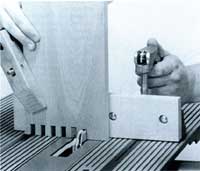
Fig. 3 The finger joint fixture in use on the Shopsmith MARK V Using The Finger Joint Fixture Cut a spacer stick that's EXACTLY the width of your fingers (in our example, 3/8"). Place the spacer stick in position against the guide pin, as shown in Fig 4-A. Position your workpiece against the spacer stick, clamp it firmly to the fixture and make your first cut. CAUTION: The upper saw guard is removed when using this fixture. Work with extreme caution! This first cut will leave an "L-shaped" notch on the end of your workpiece that's exactly the width of your fingers (in our example, 3/8"). For your second cut, loosen the clamp, remove the spacer and move your first workpiece to the right until your "L-shaped" notch rests over the guide pin. Place your second (mating) workpiece in front of the piece you just cut with its edge resting against the left side of the guide pin, as shown in Fig 4-B. Clamp your two workpieces to the fixture and make your second cut. For each subsequent finger, move both workpieces one notch to your right, clamp them in position and make your cut.
Fig. 4 Make your first cut with a spacer stick between the workpiece and guide pin (A). Make subsequent cuts as shown (B). This type of fixture will also work quite well with router tables. Dimensions and actual construction may have to vary somewhat to suit your router table setup.
|